](MXTAP_missing_manual/MXTAP-Layout.png)
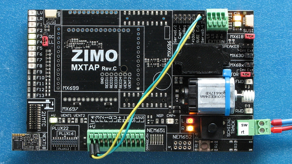
Some additional usage information about ZIMOs decodertester MXTAP.
PDF version: https://dimo.vgbahn.de/2022Heft2/ZIMO/MXTAP_missing_manual.pdf
| Reference | Pin | Location | Description |
|---|---|---|---|
| SUSI | A,2 | Zugbus / SUSI | |
| Servo1 | A,9 | ??? | |
| Servo2 | A,9 | ??? | |
| Cap+ | A,9 | ??? | |
| Cap– | A,9 | ??? | |
| GND | A,10 | Betriebsspannung Minus (Gemeinsamer Leiter für Funktionen) | |
| +V | A,10 | Betriebsspannung Plus (Gemeinsamer Leiter für Funktionen) | |
| +10V | A,10 | ??? | |
| GND | A,10 | Betriebsspannung Minus (Gemeinsamer Leiter für Funktionen) | |
| SUSI C | A,10 | Zugbus Takt / SUSI Clock | |
| SUSI D | A,10 | Zugbus Daten / SUSI Data | |
| Servo3 | A,10 | ??? | |
| Servo4 | A,10 | ??? | |
| EXTERN | LS | A,11 | Externer Lautsprecher |
| EXTERN | LS | A,11 | Externer Lautsprecher |
| EXTERN | M+ | A,11 | Externer Motor Plus |
| EXTERN | M– | A,11 | Externer Motor Minus |
| SUSI | A,13 | Zugbus / SUSI | |
| 21MTC | FG,1 | Decoder (21MTC Plug) | |
| SCHIENE TRACK |
G,13 | Programmer or Central Station | |
| NEXT18 | H,13 | Decoder (NEXT18 or NEXT18–S Plug) | |
| PLUX22 PLUX16 PLUX12 |
H,2–3 | Decoder (PLUX22, PLUX16 or PLUX12 Plug) | |
| F4 \ +V | H,4 | Decoder (wire) Betriebsspannung Plus or AUX4 | |
| F3 | H,5 | Decoder (wire) AUX3 Output | |
| F2 | H,5 | Decoder (wire) AUX2 Output | |
| F1 | H,5 | Decoder (wire) AUX1 Output | |
| LR | H,5 | Decoder (wire) F0r Output | |
| LV | H,6 | Decoder (wire) F0f Output | |
| M+ | H,6 | Decoder (wire) Motor Plus | |
| M– | H,6 | Decoder (wire) Motor Minus | |
| SR | H,6 | Decoder (wire) Schiene rechts | |
| SL | H,7 | Decoder (wire) Schiene links | |
| LS | H,7 | Decoder (wire) Lautsprecher | |
| LS | H,7 | Decoder (wire) Lautsprecher | |
| NEM651 | H,7–8 | Decoder (NEM651 Plug) | |
| NEM652 | H,9–10 | Decoder (NEM652 Plug) |
| Reference | Location | Setting | Description |
|---|---|---|---|
| OC/LL | B,2 | OC | AUX3 and AUX4 are open colector outputs (eg. Plux22 decoders) |
| OC/LL | B,2 | LL | AUX3 and AUX4 are logic level outputs (eg. some 21MTC decoders) |
| MX618 | B,13 | open | ??? |
| MX618 | B,13 | closed | ??? Enable driver for logic level outputs AUX5 and AUX6 for Next18 decoders |
| Speaker | C,13 | open | No Speaker is used (eg. Next18 decoders) |
| Speaker | C,13 | Int. | Internal Speaker is used |
| Speaker | C,13 | Ext. | External Speaker (connected to LS, LS) is used |
| MX630 | C,13 | open | ??? |
| MX630 | B,13 | closed | ??? |
| MX68x | C,13 | open | ??? |
| MX68x | B,13 | closed | ??? |
| Motor | D,13 | open | No Motor is used |
| Motor | D,13 | Int. | Internal Motor is used |
| Motor | D,13 | Ext. | External Motor (connected to M+, M–) is used |
| Reference | Location | Description |
|---|---|---|
| G,11 | Power on/off (diconnects SCHIENE TRACK) |
| Reference | Location | Description |
|---|---|---|
| LV | A,1 | Function F0f is activated |
| LR | A,1 | Function F0r is activated |
| F1 | A,1 | Function AUX1 is activated |
| F2 | B,1 | Function AUX2 is activated |
| F3 | B,1 | Function AUX3 is activated |
| F4 | B,1 | Function AUX4 is activated |
| F5 | C,1 | Function AUX5 is activated |
| F6 | C,1 | Function AUX6 is activated |
| F7 | C,1 | Function AUX7 is activated |
| F8 | D,1 | Function AUX8 is activated |
| +V | G,2 | Betriebspannung Plus connected (eg. NEM652 decoder) |
| CAP+ | G,8 | ??? |
| L | G,10 | Power from SCHIENE TRACK applied (links is positiv) |
| R | G,10 | Power from SCHIENE TRACK applied (rechts is positiv) |
| Clk | A,12 | Zugbus Takt / SUSI C aktivity or AUX3 Output |
| Data | A,12 | Zugbus Daten / SUSI D aktivity or AUX4 Output |
| FWD | E,13 | Motor driven in forward direction |
| RWD | F,13 | Motor driven in reverse direction |
The section shows how to test a decoder with NEM652 plug. A ESU LokPilot DCC V4.0 (order number 54611) with all CVs set to default is used in the section as example.
Connect green wire to F1 (when green wire is available and not connected to NEM652 plug).
Connect violet wire to F2 (when existing).
Connect speaker wires to LS and LS (when existing).
Leave all other connectors open (empty).
Start Programming Software (JMRI for Example).
Press Button on MXTAP until Leds L and R lights up.
First try to identify decoder or read some CVs.
Open Throttle.
For more details see:
Equivalent circuit diagram (PDF)
The section shows how to test a decoder with NEM651 plug. A ESU LokPilot micro DCC V4.0 (order number 54684) with all CVs set to default is used in the section as example.
Connect green wire to F1 (when existing).
Connect violet wire to F2 (when existing).
Connect speaker wires to LS and LS (when existing).
Leave all other connectors open (empty).
Start Programming Software (JMRI for Example).
Press Button on MXTAP until Leds L and R lights up.
First try to identify decoder or read some CVs.
Open Throttle.
For more details see:
Equivalent circuit diagram (PDF)
This sections shows how to test a decoder without connector (only wires). A ZIMO MX617 is used in the section as example. Note that the MX617 uses a brown wire instead of violett for function output 2.
| Conn. | Wire Color (NEM) | Wire Color (NMRA) | Color | Function |
|---|---|---|---|---|
| +V \ F4 | Blau | Blue | Betriebsspannung Plus (Gemeinsamer Leiter für Funktionen) | |
| F3 | - | - | - | AUX 3 (Funktionsausgang) |
| F2 | Violett | - | AUX 2 (Funktionsausgang) | |
| F1 | Grün | - | AUX 1 (Funktionsausgang) | |
| LR | Gelb | Yellow | Licht hinten (Funktionsausgang) | |
| LV | Weiß | White | Licht vorne (Funktionsausgang) | |
| M+ | Orange | Orange | Motor Plus | |
| M- | Grau | Gray | Motor Minus | |
| SR | Rot | Red | Schiene rechts | |
| SL | Schwarz | Black | Schiene links | |
| LS | Braun | - | Lautsprecher | |
| LS | Braun | - | Lautsprecher |
Leave all other connectors open (empty).
Start Programming Software (JMRI for Example).
Press Button on MXTAP until Leds L and R lights up.
First try to identify decoder or read some CVs.
Open Throttle.
For more details see:
Equivalent circuit diagram (PDF)
This section shows how to test a decoder with Next18 (no Next18-S) connector. See RCN-118 for details. A ZIMO MX618N18 with all CVs set to default (expect CV #124 where Bit 7 is set to 1 “Logik-Pegel anstelle SUSI aktiviert”) is used as example.
Start Programming Software (JMRI for Example).
Press Button on MXTAP until Leds L and R lights up.
First try to identify decoder or read some CVs.
Open Throttle.
For more details see:
Equivalent circuit diagram (PDF)
This section shows how to test a decoder with Next18-S (no Next18) connector. See RCN-118 for details. A ESU LokSound micro V4.0 (with all CVs set to default ???) is used as example.
Start Programming Software (JMRI for Example).
Press Button on MXTAP until Leds L and R lights up.
First try to identify decoder or read some CVs.
Open Throttle.
For more details see:
Equivalent circuit diagram (PDF)
See hint about F3 and F4 shown on SUSI LEDs in section about Next18.
This section shows how to test a decoder with PluX22, PluX16 or PluX12 connector. See RCN-122 for details. A ESU LokPilot V4.0 DCC (order number 54617) with all CVs set to default is used as example.
Start Programming Software (JMRI for Example).
Press Button on MXTAP until Leds L and R lights up.
First try to identify decoder or read some CVs.
Open Throttle.
For more details see: